Anyone who develops their own control systems for electric drives knows the problem: as soon as the test bench takes over, the view of internal software states disappears — precisely when it is needed for fault-finding. A cross-domain test approach connects measurement data and controller variables on one timeline. This makes it possible to analyze causes instead of symptoms and to optimize parameters during running operation, without recompiling or restarting.
"As soon as the real motor runs, the controller becomes a black box — every correction costs a complete iteration cycle. The solution does not lie in more simulation, but in making software internals and physical measurement data visible synchronously on one timeline. In this way, many iterations become one targeted one."
Joshua Summa, CEO and Co-Founder, es:saar
Testing motor controllers in drive systems follows a familiar path: from modeling the drive system, through MiL, SiL and HiL tests, all the way to the real test bench. As long as the system runs in simulation, the software behavior can be observed directly. At the test bench this changes: there, as a rule, only physical measurement quantities are available. The problem: deviations between simulation and real behavior are difficult to trace, because the internal variable behavior of the software is not directly measurable at the physical test bench. At most it is inferred. Suitable methods for making measurements of runtime variables accessible have so far been either unavailable to many development teams or too costly to integrate. Cross-domain testing addresses this: in this approach, runtime variables are captured as measurement signals from the software domain and synchronized with measurement signals from the physical domain on one timeline. This enables controller tuning, sensor calibration and validation directly at the test bench and at runtime, and with it allows developers to reach real system testing earlier, starting from the model. This article shows what that means in practice, and how it shortens the path from model to qualified system.
The controller is designed. The drive system has been modeled or identified through measurements, the controller software developed, and the simulation shows what was expected. Then the developer’s own controller meets the real motor. The speed overshoots during ramp-up; a whine can be heard. The phase current lies within the expected range, but what happens internally in the controller remains invisible. It becomes apparent that this is a tuning problem, so several loops follow: adjust, compile, flash, restart, wait, measure. And back to the beginning.
This scenario has a price: longer development cycles, higher test costs, greater dependency on HiL infrastructure that not every team can operate. Anyone with access to a HiL station shifts the qualification and calibration effort into the simulation, but without any guarantee that the real behavior is satisfactorily represented and that the simulation is sufficient. This is one of the main reasons why teams decide against in-house development: not because the control engineering as such is too complex, but because the test effort from a working model to a qualified system is too high. Anyone who develops their own motor control has more degrees of freedom than someone who uses a bought-in motion controller. With a complex controller and many parameters, that multiplies quickly. And at some point a strategic decision stands in the room: is in-house development worthwhile at all, or is it better to buy?
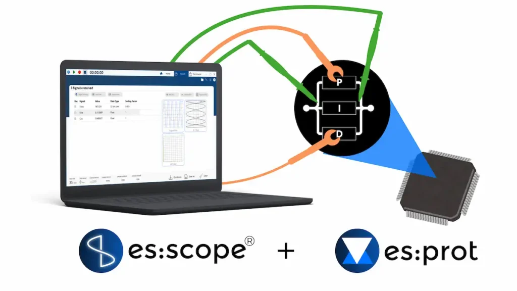
To make runtime variables accessible as interpretable measurement values and setpoints, the open middleware es:prot can be used. It can be integrated into the C code of any microcontroller. For each signal, what it means as a data point is defined in the software configuration: name, type, scaling factor. Variables are tapped from the code and passed to a configurable protocol for data transfer, optimally by means of DMA-based data transport. This software-based approach eliminates the need for external debug or trace probes, symbol files, or execution stops for data access. The data is exchanged cyclically at a high data rate and received by the data acquisition software es:scope on a computer via a serial interface or network.
The data exchange is bidirectional: via es:scope and by means of es:prot, parameters can be adjusted at runtime and commands sent directly to the running system. The result: the system continues to operate without interruption while its variables are observed in real time and controlled asynchronously.
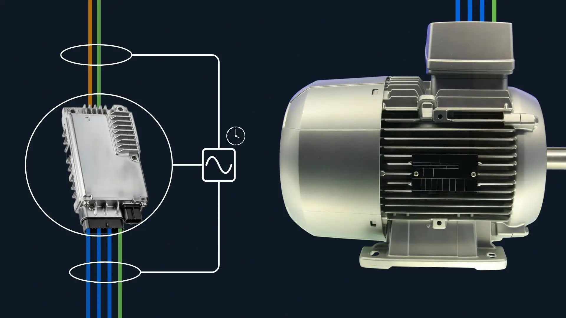
The software-based approach makes runtime variables accessible as measurement values. But complete insight into system behavior only arises when these are displayed together with physical measurement signals on a common timeline. Only then can causality be recognized: when a problem occurs, and exactly when and which software behavior led to it. That is the principle of cross-domain testing (CDT). The basis for this is a common protocol: both the controller software and es:mod, the DAQ system from es:saar, use es:prot for data transmission. es:mod additionally relies on IEEE 1588 PTP for network-based time synchronization. From es:scope 2.0 onwards, multiple data sources can thus be brought together on a common timeline.
A cross-domain test bench for motor applications can be built directly with the tools described. The typical setup consists of a DUT controller with integrated es:prot, the DUT motor, an inverter for motor control, a computer with es:scope, and es:mod as the central DAQ system for sensor signals. es:mod takes on two roles here: as a data acquisition device for sensor signals, and as an inverter with a three-phase bridge for driving the counter-motor.
Ramp-up begins, the speed overshoots. That is a known calibration problem with many possible causes. And a whine can be heard whose origin cannot be grasped from outside. The phase current shows an anomaly, but what happens internally in the controller remains invisible. So: adjust, compile, flash, restart, wait, measure. Until the overshoot is within tolerance. With the whine, nothing changes at first. Another iteration.
With CDT this changes. The behavior of the speed controller is directly visible and displayed synchronized with the measured speed on the same timeline. The parameters are calibrated in a single iteration at runtime, and the overshoot is thereby reduced into the tolerance range. The cause of the whine is finally identified, because with CDT the measured rotor position, applied voltage and resulting current are displayed on one timeline. It becomes apparent that the position sensor is drifting — that is, the position assumed by the controller deviates from the actual one, and voltage and current no longer match. The cause is identified, the parameter corrected, the effect tested immediately. What previously required many loops becomes a few targeted interventions. Since the insight into the software behavior is retained, the path from the model to the qualified system becomes more transparent and qualification costs fall. The excessive test effort on the real system previously forced strategic decisions against in-house development. CDT addresses exactly this. It can be tested on the real system earlier. The threshold to in-house development sinks. And with it the dependency on bought-in solutions.
01 With controller variables and measurement signals on one timeline, faster from model to qualified system
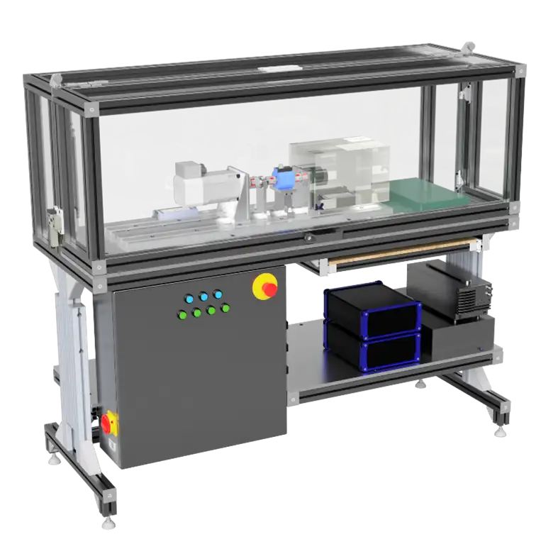
02 Besides software, es:saar also offers complete test benches
 English
  Deutsch